Meshes
Overview
This chapter explains particle masks and how to create mesh – by importing or by paramteric construction.
STL import
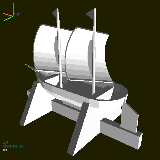
STL (STereoLitography) file format is an interchange format for triangulated surfaces in 3d. It is used as a possible export format in many CAD systems. There is a single function for their import, woo.utils.importSTL which return list of facet particles, which can be added to the simulation instantly:
S.dem.par.add(woo.utils.importSTL('your-model.stl'),mat=woo.utils.defaultMaterial())

Fig. 5 Mesh imported from the STL file.
The woo.utils.importSTL function has options for scaling, shifting, rotating and assigning colors – check its documentation for details.
Parametric surfaces
GNU Triangulated Surface library is a library for constructing and manipulating triangulated surfaces. There are a few convenience functions in Woo for converting lists of points into a GTS surface, which can be again converted to list of facets easily, and added to the simulation.
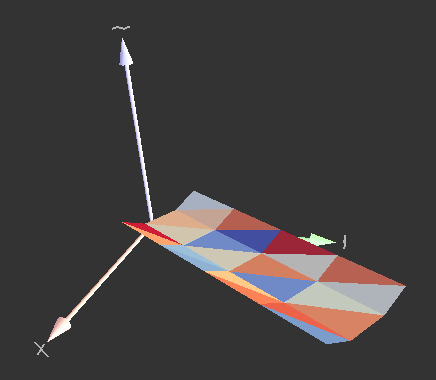
For example, let’s create V-shaped conveyor bed with flat bottom. Let’s work in local coordinates first, so that \(x\)-axis is the conveyor axis, \(y\) is horizontal and \(z\) is vertical. The dimensions of the bed will be:
botWd, flat bottom widthsideWd, elevated side widthsideHt, elevated side height
The bed will start at \(x=0\) and will go up to \(x=x_1\) (x1) with xDiv segments:
# set parameters
Woo[1]: botWd=.3; sideWd=.2; sideHt=.1; x1=2; xDiv=5

Woo[2]: import numpy

# x points where polylines will be defined
Woo[3]: xx=numpy.linspace(0,x1,num=xDiv)

Woo[4]: print(xx)
[0.  0.5 1.  1.5 2. ]

# for each x, create the polyline with 4 points
Woo[5]: pts=[[(x,-.5*botWd-sideWd,sideHt),(x,-.5*botWd,0),(x,.5*botWd,0),(x,.5*botWd+sideWd,sideHt)] for x in xx]

Woo[6]: print(pts)
[[(0.0, -0.35, 0.1), (0.0, -0.15, 0), (0.0, 0.15, 0), (0.0, 0.35, 0.1)], [(0.5, -0.35, 0.1), (0.5, -0.15, 0), (0.5, 0.15, 0), (0.5, 0.35, 0.1)], [(1.0, -0.35, 0.1), (1.0, -0.15, 0), (1.0, 0.15, 0), (1.0, 0.35, 0.1)], [(1.5, -0.35, 0.1), (1.5, -0.15, 0), (1.5, 0.15, 0), (1.5, 0.35, 0.1)], [(2.0, -0.35, 0.1), (2.0, -0.15, 0), (2.0, 0.15, 0), (2.0, 0.35, 0.1)]]

# convert list of polylines to a gts surface (all must have the same number of points)
Woo[7]: surf=woo.pack.sweptPolylines2gtsSurface(pts)

Woo[8]: print(surf)
<gts.Surface object at 0x7fba4f913f90>

# convert surface to facets and add them to the scene
Woo[9]: S.dem.par.add(woo.pack.gtsSurface2Facets(surf))
Out[9]:
[0,
 1,
 2,
 3,
 4,
 5,
 6,
 7,
 8,
 9,
 10,
 11,
 12,
 13,
 14,
 15,
 16,
 17,
 18,
 19,
 20,
 21,
 22,
 23]
If one wants to convert from local to global coordinates, define local coordinates via Node and pass it as the localCoords parameter to woo.pack.sweptPolylines2gtsSurface:
Woo[10]: node=Node(pos=(.2,.2,.2),ori=((0,0,1),math.pi/3.))

Woo[11]: surf=woo.pack.sweptPolylines2gtsSurface(pts,localCoords=node)
or use the node object manually to convert all points:
Woo[12]: pts=[[node.loc2glob(p) for p in pp] for pp in pts]

Woo[13]: surf=woo.pack.sweptPolylines2gtsSurface(pts)
Behind the scenes, loc2glob does nothing else than transforming the local point \(p'\) using the local origin position \(O\) and orientation \(q\) as
or, in Python, n.ori*(p+n.pos).
Note
Quaternions are constructed from the Axis-angle representation of rotations; angles are always given in radians. Thus e.g. Quaternion((0,0,1),math.pi/3.) rotates around the \(z\)-axis by \(\frac{\pi}{3}\equiv60°\).
In summary, the conveyor code looks like this, in a compact way:
botWd=.3; sideWd=.2; sideHt=.1; x1=2; xDiv=5
import woo; from woo.core import *; from woo.dem import*; import woo.utils; import numpy; import math
S=woo.master.scene=Scene(fields=[DemField()])
xx=numpy.linspace(0,x1,num=xDiv)
pts=[[(x,-.5*botWd-sideWd,sideHt),(x,-.5*botWd,0),(x,.5*botWd,0),(x,.5*botWd+sideWd,sideHt)] for x in xx]
node=Node(pos=(.2,.2,.2),ori=((0,0,1),math.pi/3))
surf=woo.pack.sweptPolylines2gtsSurface(pts,localCoords=node)
S.dem.par.add(woo.pack.gtsSurface2Facets(surf))

Fig. 6 Conveyor bed mesh created parametrically by the script above.
Note on particle masks
Particle.mask is a bit array which determines which particles may have contacts with other particles. Mask is a regular (integer) number in the memory, but is interpreted as individual bits, for example like this:
0000 0010     = 2 in decimal
0000 0011     = 3 in decimal
0000 0110     = 6 in decimal
Binary numbers can be written in python directly, e.g. 0b0010 would be the first bit array, equal to 2 in decimal.
There are two basic rules:
Particles collide only if they have a common bit (that is, if their bitwise AND is nonzero:
maskA & maskB !=0).If a common bit is contained in
DemField.loneMask, the particles will not collide. This rule is to avoid collisions of particles where it is meaningless, such as facets in a mesh between themselves. With meshes, the number of spurious “contacts” can be very high (thousands) slowing down the simulation unnecessarily.
Mask bits can be further used for marking particles (e.g. with BoxOutlet, when markMask is set) in arbitrary ways.
Default values of mask are different for different particles:
Particles which usually move (
Sphere,Ellipsoid,Capsule) have the mask set toDemField.defaultMovableMask(0b0101) by default (when created using theSphere.makeetc functions). This (calledDemField.defaultInletMask) is also the default value forParticleInlet.mask(particles created during the simulation; treated later)Particles usually acting as the boundary (
Facet,Membrane,InfCylinder,Wall) set the mask toDemField.defaultBoundaryMask(0b0011) by default.DemField.loneMaskdefault toDemField.defaultLoneMask(0b0010).BoxOutlet.maskdefaults toDemField.defaultOutletMask(0b0100) (delting particles is treated in detail later).
This means that
any contacts between boundary particles (
Facet+Facetand such) are avoided, but that boundary will still interact with particles which usually move;deleters will by default only delete particles which usually move (since they contain the
0b0100bit), but not boundary particles.
If the default behavior is not sufficiently flexible for your setup, it can be always tuned by hand.
Tip
Report issues or inclarities to github.