Deposition and screeding after rotary kiln discharge
Summary
Discharge of pellets from rotary kiln was studied using the Discrete Element Method. The task was to compare four scenarios (different ways of diffusing pellet stream at discharge) regarding their deposition pattern and load on the screed wall, which serves as leveling mechanism to assure even distribution of pellets across the moving cooler. Recommendations about potential design changes were discussed based on the results.
Methodology
Based on provided 3D models, drafts and some experimental data for material calibration, the DEM model was set up. We studied four ways of distributing the discharge stream over the cooler width (and compared them with each other):
grizzly=0: empty discharge area (no grizzly bars, no beam accross); pellets will land on the cooler directly.
grizzly=1: only bar used for supporting grizzly beams in the discharge area, which spreads the stream accross the cooler width somewhat.
grizzly=2: 5 grizzly bars; the purpose of grizzly bars, in the original design, is to catch big build-ups fragments which sometimes form in the rotary kiln (rings around the refractory which subsequently fall apart), so that they don’t contaminate the product on the cooler or mechanically obstruct further processing. Grizzly bars, however, also naturally spread the rather concentrated discharge stream over the cooler width.
grizzly=3: 3 grizzly bars, with different distance, and reaching higher up to the kiln.
These scenarios can be seen 3d in Fig. 51.
The whole analysis was divided into several distinct steps, performed for each scenario:
simulate the discharge using DEM (Fig. 51);
statistically evaluate pellet stream behavior, especially in the landing area (Fig. 52); by summation along the direction of cooler’s motion, probability density function is computed (Fig. 53);
using probability density function from the previous step, simulate deposition on the cooler, this results in realistic heap profile (Fig. 54);
perform simulation where screed wall is used as leveling mechanism which should make the heap profile more or less flat (Fig. 56)
Simulations were performed, for computational reasons, with the PSD (particle size distribution) scaled 2× (discharge) or 3× (screeding). It is well known that macroscopic behavior of granular materials does not exhibit size effect (unlike nonlinear continuum), as long as surface effects of particles (such as atomic forces) don’t play significant role.
Discharge
Discharge simulations were done using imported 3D models provided by the customer, with known process parameters such as feed rate (650 t/h), particle size distribution (scaled 2×) and material parameters. Experimental data have shown that burnt pellets have the coefficient of restitution around 0.56 and angle of repose around 30°. The simulation was done using the Schwarz model, with the adhesion energy 15 J/m and Carpick–Ogletree–Salmeron’s parameter \(\alpha=0.4\).
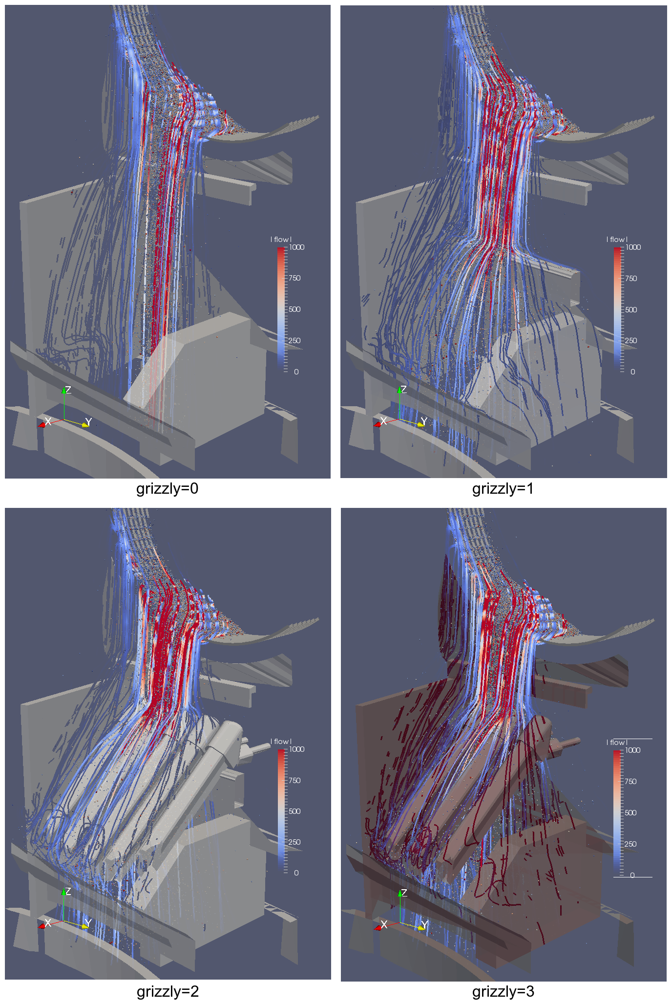
Fig. 51 Geometry and discharge results for all scenarios studied; flow lines are averages collected by woo.dem.FlowAnalysis. The kiln inner surface was ribbed in order to simulate rugged inner surface.
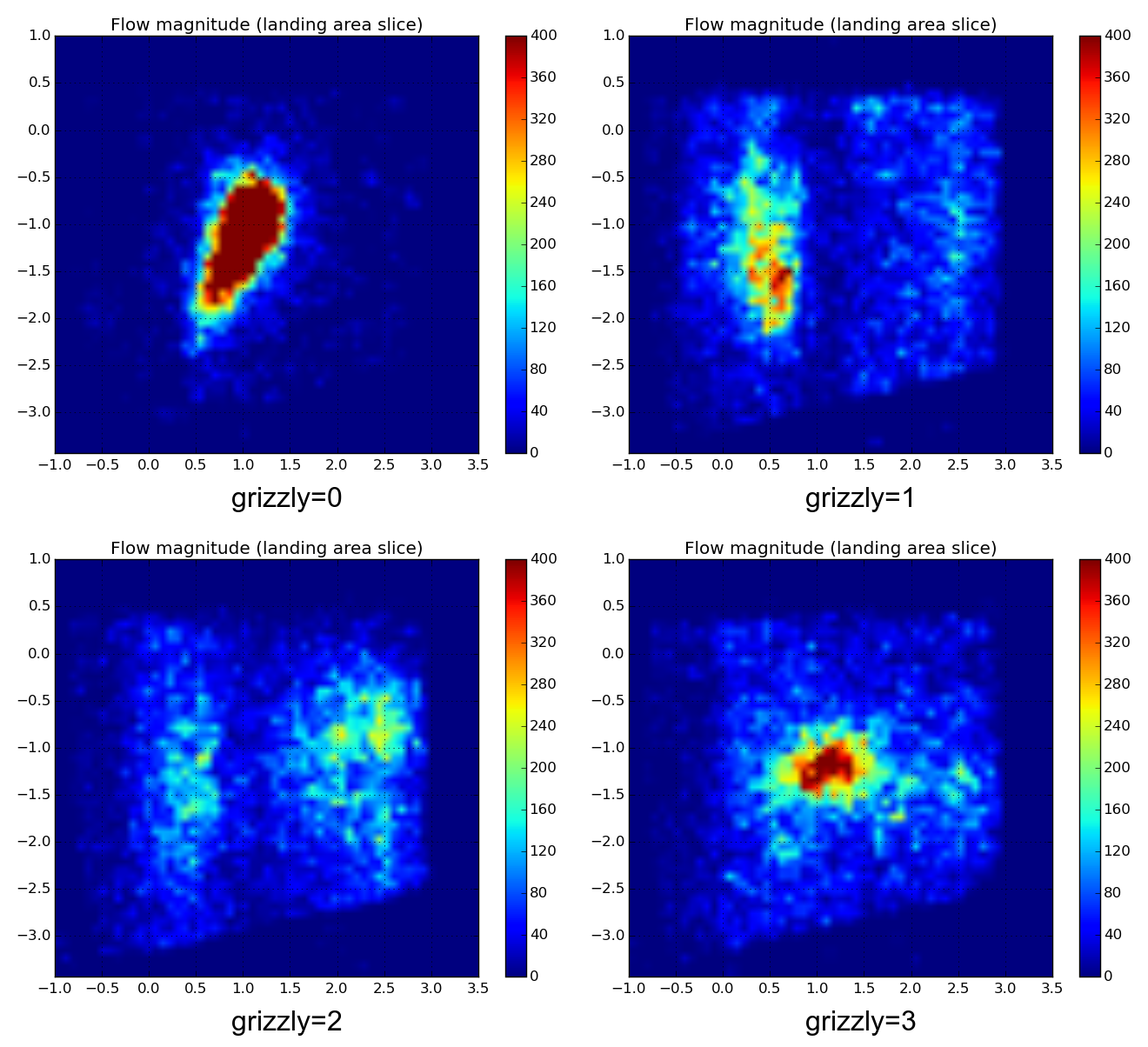
Fig. 52 Comparison of horizontal slices through the averaged flow field, at the level of the cooler (landing area) between three scenarios. The kiln (influx) is on the left.
Fig. 53 Flow intensity depending on the position on the cooler; it is visible that grizzly=0 has the most prominent maximum (single stream), the grizzly bar causes some (but small) spread, and the grizzly bars achieve the best spread (two peaks: one for pellets which fall down directly, other for those which slide down along the grizzly bars and rebound back onto the cooler).
The simulation renderings are show in Fig. 51; slice through the statistically average flow field is show in Fig. 52. The flow depending on radial position on the cooler (distance from the cooler’s center) is shown in Fig. 53.
The flow does not equal the resulting heap shape, since particles will spread by rolling over each other during deposition. This process was simulated and the resulting heaps have skylines as shown in Fig. 54.
Fig. 54 Heap skylines for different scenarios. They are similar to flow rate depending on radial position, but due to particle interactions, the profile is smoother, though maxima are always clearly identifiable. The maximum slope is determined by the angle of repose of the granular material. The gray bottom part is compact deposition on the cooler which was not simulated, as it does not take part in the redistribution process.
Screed wall
Pre-generated heaps were pushed under the screed wall. The screed wall height (30cm of the simulated space) was common for all heaps and was hand-tuned to allow all pellets to pass through without leaving significant voids. Translational velocity was scaled for computational reasons (to 0.5m/s, where inertia effects still play a rather small role; real cooler translational velocity is around 6cm/s). Only the upper layer on the cooler was simulated (it bottom moving with the cooler), the lower layer (approx. 40cm, shown gray in Fig. 54) was omitted from the simulations as it does not contribute to redistribution; simulations could therefore run significantly faster.
Visual inspection of the simulation (Fig. 59) is important to understand the screeding mechanism. Wedge-shaped arrangement forms in the vicinity of the wall (Fig. 55) which deviates linear flow of other pellets. This upward motion leads to formation of local heap (over the wedge), and once the slope exceeds the angle of repose, particles roll down, laterally, and also backwards, until they find a free place where to get under the screed wall. As the wall is perpendicular to the flow, it does not, in itself, cause lateral redistribution, only indirectly through the vertical heap build-up.
Resulting redistribution is shown in Fig. 56, average paths in Fig. 58.
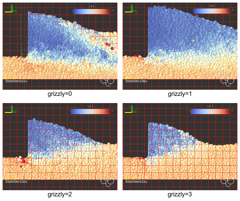
Fig. 55 Sections through the heap during screeding, colored by velocity (orthographic view). In all scenarios, wedge-shaped area of slow-moving pellets, due to the proximity of the wall, are visible. These are potential areas for sintering (not simulated), and are also the main mechanism by which the pellets redistribute vertically and, eventually, laterally.
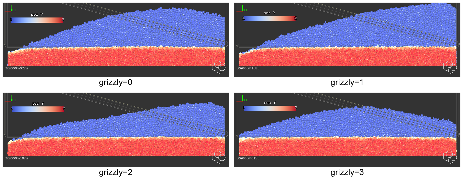
Fig. 56 Heap redistribution (front orthographic view). The back plane (blue) is heap shape immediately behind the screed wall, the red particles are in the front (on the stream tip). The spreading is (almost) perfect, leving no or very little void area in the left corner.
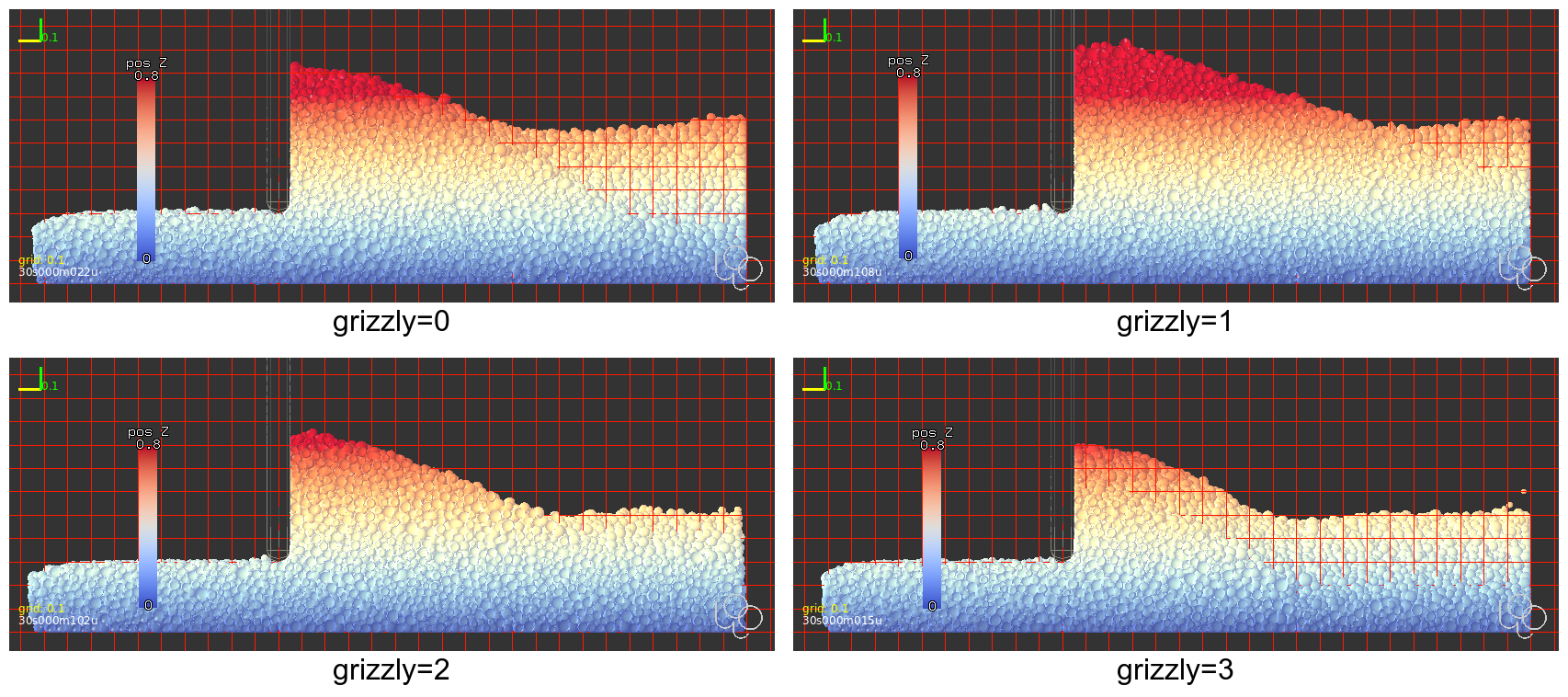
Fig. 57 Heap redistribution (lateral orthographic view).
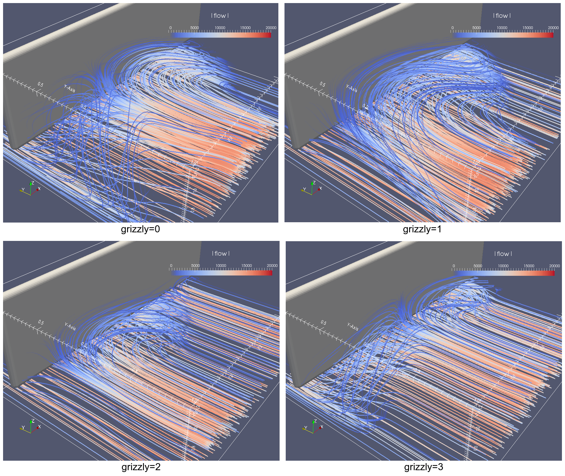
Fig. 58 Average redistribution paths of pellets. grizzly=0 shows great redistribution to both sides, grizzly=1 has great redistribution, but only to the right, grizzly=2 has a little redistribution and grizzly=2 has the least.
Todo
upload videos to Vimeo
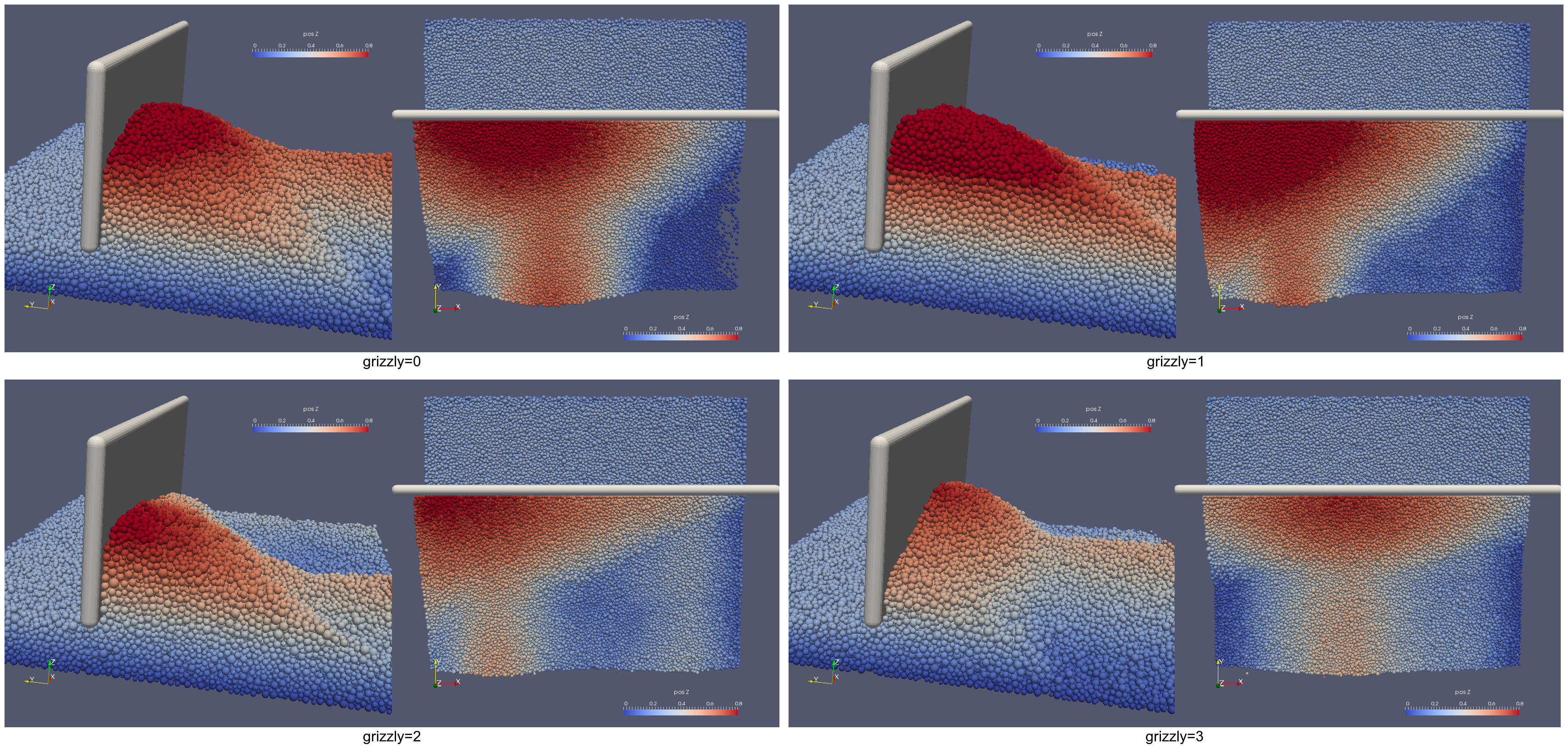
Fig. 59 3d animations of the simulation will be avilable from Vimeo (WIP). Coloring by the \(z\)-coordinate makes the leveling visible. These images correspond to the final state (t=30s).
We were recording force acting on the wall, shown in Fig. 60. Those values show clearly that grizzly bars alleviate the load on the screed wall significantly. The load on the wall itself is not problematic as such, but high confinement and small relative motion of pellets on the wall may lead to partial sintering, as their temperature is still high, and the appearance of pellet clusters. Sintering effects were not included in the simulations.
Fig. 60 Force acting perpendicular to the screed wall; zero at the beginning is the time before the heap tip arrives, it then increases and stabilizes. Although the values have to be taken with grain of salt, they are useful for comparison of different scenarios between themselves.
The grizzly=1 scenario (grizzly support beam only) is worse than grizzly=0 in terms of force — pellets are accumulated more or less in one place only for both cases (see Fig. 54) but the tip is closer to the edge for grizzly=1, making the redistribution much less efficient.par The curves have not yet converged to the final value, there are still some pellets accumulating behind the screed wall; the overall trend and force ration between scenarios is, however, clear.
Conclusions
Grizzly bars provide a relatively good way to spread out particle stream across the cooler width, measured by evenness of the heap profile, and by force acting on the screed wall. The new design (grizzly=3) has slightly better performance than the curretn state (grizzly=2) in terms of material accumulation behind the wall, and is similar in force acting on the wall. The tip of the heap is more in the middle of the cooler for grizzly=3, which explains the improvement.
Scenarios without grizzly bars lead to more accumulation of material. The case with grizzly support beam only (grizzly=1) is worse in terms of screed force than the scenario with everything removed (grizzly=0), and both are significantly worse than scenarios with grizzly bars.
Screeding mechanism consists in formation of low-velocity confined wedge at the wall (it is confined by the wall and the pellet stream from the other side), which pushes incoming pellets upwards; they subsequently roll laterally (or backwards, in the sense of gradient) when the heap slope is greater than the angle of repose. The screed wall is perpendicular to the movement of particles, which is the least efficient configuration in terms of lateral redistribution.
Simulations don’t predict whether sintering occurs at the screed wall (in the confined wedge in particular) in the absence of grizzly bars due to higher forces.
If grizzly bars are to be removed, redistribution should be eased by either turning the screed wall slightly, or making it plough-shaped with the tip in the expected heap peak to spread pellets sideways, away from that point. Design of an efficient shape would be a subject of further studies.
The shape/orientation of the screed wall could nevertheless be still improved, even for the scenario with grizzly bars. That would be subject of further studies.
Tip
Report issues or inclarities to github.